ABSTRACT
Box shifting mechanism is widely
used in industries instead of conveyors. This project relates to improvement in
transfer jobs, and it relates particularly to devices for transferring set of
boxes or bottles for filling processes.
This mechanism have several
advantages in manufacturing line of bottling or other eatable or medicinal
products where an ingredient is added at one position of bottle and the other ingredient at other
position. In the past many different types of box transfer mechanisms have been
used.
This box shifting mechanism is
operated by four bar mechanism. In our project four bar mechanism using in
various linkages, which converts rotary motion into reciprocating motion. We
had just implemented our basic mechanical knowledge and designing skills for
designing and fabricating this project
TABLE OF CONTENTS
CHAPTER TITLE PAGE NO
NO
ABSTRACT
1 INTRODUCTION
1.1 Box shifting
mechanism 1
1.2
Conveyor System 3
1.3 Industries that
use
Conveyor
systems 4
1.4 Care and
maintenance 5
1.5 Poor take-up
adjustment 6
1.6 Lack of
lubrication 6
1.7 Contamination 6
1.8 Product
Handling 7
1.9 Drive Train 7
1.10 Tracking or
Timing 8
1.11 Growth of
conveyor systems 8
2 METHODS AND MATERIALS
2.1 Four-bar linkage 10
2.2 Inversion of Four Bar Mechanism 11 2.2.1
Double Crank Mechanism 13
2.2.2
Crank-Rocker Mechanism 14 2.2.3 Double-Rocker
Mechanism 15
2.2.4
Parallel Crank Mechanism 16
2.3
Position analysis of
Grashof four
bar mechanism 16
2.4 Planar four-bar linkage 19
2.5 Planar quadrilateral linkage 20
2.6 Design of four bar mechanisms 20 2.7 Systematic
Diagram 21
2.8 Design and Fabrication
Methodology 22
2.9 Selection of Materials 23
2.9.1 Linkages 23
2.9.2 Dc motor 24
2.9.3 Dc battery 24
2.9.4 Steel
Frame 25
2.10 Work Plan 25
3 APPLICATIONS & ADVANTAGES 28
4 REFERENCES & CONCLUSION 29
5 PHOTO GRAPH 30
DESIGN AND FABRICATION OF BOX SHIFTING MECHANISM VIDEO EXPLANATION
CHAPTER 1
INTRODUCTION
1.1 Box
shifting mechanism
This
invention relates to improvements in transfer and conveying devices, and it
relates particularly to devices for transferring set-up cardboard boxes from a
box folding or forming machine to the operator of a semi-automatic box wrapping
machine. A great many manufacturers of fancy wrapped or covered cardboard boxes
used for packaging candies, cakes, and other confections, cosmetics and other
articles are equipped with the so called quad staying machines by means of
which a box blank is folded or set-up into boxlike form. These set-up boxes are
transferred by means of a conveyor to an operator, who picks up the boxes and
places and centres them on wrappers with which the boxes are to be covered. The
boxes and wrappers are then conveyed to a box wrapping machine where the
wrapper is folded around and glued to the box. Usually, the operation of the
wrapping machine is controlled by means of a switch actuated by the box forming
machine so that their operating speeds are related to each other.
Fully
automatic machines are available for both setting up the boxes, placing them on
the wrappers and feeding the assembly to the wrapping machine. In many
instances, however, the cost of replacement of the semi-automatic machines with
fully automatic machines, is so great that it cannot be justified by the
increased rate of production possible with automatic machines.
The
principal difference in the rate of operation of the fully automatic machines
and the semi-automatic machines resides in the human factor, namely, the
operator or feeder of the semiautomatic wrapping machine. Considerable manual
dexterity and skill are required to pick up the boxes and centre them
accurately on the wrappers as they move past the operator's station. The
movements of the operator are further dependent upon the position of the setup
boxes with respect to the operator. With the usual conveyor arrangement, it is
necessary for the operator to reach across the conveyor which feeds the wrapping
machine and pick up a box from the conveyor leading from the quad. Inasmuch as.
The operator must reach across the conveyor to pick up the boxes, the speed of
the operator is decreased. Moreover, the constant reaching and stretching for
the boxes is very tiring so that the operator can Work for only .a relatively
short period of time. This requires the service of another operator or shutting
down of the machines.
We have
found that when. The set-up boxes are. Four points into a position which is
closer to the operator and more conveniently located with respect to the
conveyor for feeding the wrapping machine, the efficiency of the operator is
greatly increased, the work is made less tiresome and the output of wrapped
boxes can be increased to such an extent that it is closely, comparable to that
of the fully automatic machines.
The present
invention, therefore, has as its principal object the provision of a device
which can be used with box forming and semi-automatic wrapping machines to
transfer the set-up boxes from the conveyor of the box-forming machine into a
position which enables the operator to, pick up and place the boxes on the
wrappers with a minimum of reaching and resulting fatigue.
Other
objects of the invention, and the advantages thereof, will become apparent from
the following description of a typical device embodying the present invention.
In
accordance with the present invention, I have provided an article-controlled
transfer mechanism, by means of which the boxes being advanced by the conveyor
of the box-forming machine, are transferred into a position in front of the
operator of the wrapping machine and closely adjacent to the wrappers carried
by the feed conveyor of the wrapping machine so that the operator can pick up
the boxes and transfer them directly to the wrapper with a minimum of reaching
and other movements.
More
particularly, the transfer mechanism includes a pusher member controlled by
means of an electric eye which pushes the set-up boxes from the conveyor from
the box-forming machine on to a table or platform to form an advancing row of
boxes, the nearest one being directly in front of the operator so that it can
be picked up by the operator and transferred to the conveyor of the wrapping
machine.
Moreover,
the transfer mechanism can be controlled independently by the operator to
render it ineffective when a damaged or improperly formed box is discharged
from the box former or toby-pass and accumulate boxes when the wrapping machine
is shut down for reloading, adjustment or the like.
My transfer
mechanism has been found to increase greatly the rate of production of the
wrapped boxes so that the production rate is comparable to that of a fully
automatic machine, while, at the same time, it is considerably less tiring to
the operator
1.2 Conveyor System
A conveyor
system is a common piece of mechanical handling equipment that moves materials
from one location to another. Conveyors are especially useful in applications
involving the transportation of heavy or bulky materials. Conveyor systems
allow quick and efficient transportation for a wide variety of materials, which
make them very popular in the material handling and packaging industries. Many
kinds of conveying systems are available, and are used according to the various
needs of different industries.
Similarly
the same kind of operation done by this box shifting mechanism. This box
shifting machine helps in transfer of boxes smoothly by use of four bars with a
simple arrangement. But it operated by four bar mechanism which converts rotary
motion into reciprocating motion.
1.3
Industries that use conveyor systems
Conveyor
systems are used widespread across a range of industries due to the numerous
benefits they provide. Conveyors are able to safely transport materials from one
level to another, which when done by human labor would be strenuous and
expensive. They can be installed almost anywhere, and are much safer than using
a forklift or other machine to move materials.
They can
move loads of all shapes, sizes and weights. Also, many have advanced safety
features that help prevent accidents. There are a variety of options available
for running conveying systems, including the hydraulic, mechanical and fully
automated systems, which are equipped to fit individual needs.
Conveyor
systems are commonly used in many industries, including the automotive,
agricultural, computer, electronic, food processing, aerospace, pharmaceutical,
chemical, bottling and canning, print finishing and packaging. Although a wide
variety of materials can be conveyed, some of the most common include food
items such as beans and nuts, bottles and cans, automotive components, scrap
metal, pills and powders, wood and furniture and grain and animal feed.
Many factors
are important in the accurate selection of a conveyor system. It is important
to know how the conveyor system will be used beforehand. Some individual areas
that are helpful to consider are the required conveyor operations, such as
transportation, accumulation and sorting, the material sizes, weights and
shapes and where the loading and pickup points need to be.
1.4 Care and
maintenance
A conveyor
system is often the lifeline to a company’s ability to effectively move its
product in a timely fashion. The steps that a company can take to ensure that
it performs at peak capacity, include regular inspections, close monitoring of
motors and reducers, keeping key parts in stock, and proper training of
personnel.
Increasing
the service life of your conveyor system involves: choosing the right conveyor
type, the right system design and paying attention to regular maintenance
practices.
A conveyor
system that is designed properly will last a long time with proper maintenance.
Here are six of the biggest problems to watch for in overhead type conveyor
systems including I-beam monorails, enclosed track conveyors and power and free
conveyors.
1.5 Poor take-up adjustment:
This is a
simple adjustment on most systems yet it is often overlooked. The chain take-up
device ensures that the chain is pulled tight as it leaves the drive unit. As
wear occurs and the chain lengthens, the take-up extends under the force of its
springs. As they extend, the spring force becomes less and the take- up has
less effect. Simply compress the take-up springs and your problem goes away.
Failure to
do this can result in chain surging, jamming, and extreme wear on the track and
chain. Take-up adjustment is also important for any conveyor using belts as a
means to power rollers, or belts themselves being the mover. With poor-take up
on belt-driven rollers, the belt may twist into the drive unit and cause
damage, or at the least a noticeable decrease or complete loss of performance
may occur. In the case of belt conveyors, a poor take-up may cause drive unit
damage or may let the belt slip off of the side of the chassis.
1.6 Lack of lubrication:
Chain
bearings require lubrication in order to reduce friction. The chain pull that
the drive experiences can double if the bearings are not lubricated. This can
cause the system to overload by either its mechanical or electrical overload
protection. On conveyors that go through hot ovens, lubricators can be left on
constantly or set to turn on every few cycles.
1.7 Contamination:
Paint,
powder, acid or alkaline fluids, abrasives, glass bead, steel shot, etc. can
all lead to rapid deterioration of track and chain. Ask any bearing company
about the leading cause of bearing failure and they will point to
contamination. Once a foreign substance lands on the raceway of a bearing or on
the track, pitting of the surface will occur, and once the surface is
compromised, wear will accelerate. Building shrouds around your conveyors can
help prevent the ingress of contaminants. Or, pressurize the contained area
using a simple fan and duct arrangement. Contamination can also apply to belts
and of the motors themselves.
Since the
motors can generate a considerable amount of heat, keeping the surface clean is
an almost-free maintenance procedure that can keep heat from getting trapped by
dust and grime, which may lead to motor burnout.
1.8 Product Handling:
In conveyor
systems that may be suited for a wide variety of products, such as those in
distribution centers, it is important that each new product be deemed
acceptable for conveying before being run through the materials handling
equipment. Boxes that are too small, too large, too heavy, too light, or too
awkwardly shaped may not convey, or may cause many problems including jams,
excess wear on conveying equipment, motor overloads, belt breakage, or other
damage, and may also consume extra man-hours in terms of picking up cases that
slipped between rollers, or damaged product that was not meant for materials
handling.
If a product
such as this manages to make it through most of the system, the sortation
system will most likely be the affected, causing jams and failing to properly
place items where they are assigned. It should also be noted that any and all
cartons handled on any conveyor should be in good shape or spills, jams,
downtime, and possible accidents and injuries may result.
1.9 Drive Train:
Notwithstanding
the above, involving take-up adjustment, other parts of the drive train should
be kept in proper shape. Broken O-rings on a Line shaft, pneumatic parts in
disrepair, and motor reducers should also be inspected. Loss of power to even
one or a few rollers on a conveyor can mean the difference between effective
and timely delivery, and repetitive nuances that can continually cost downtime.
Bad Belt
1.10 Tracking or Timing:
In a system
that uses precisely controlled belts, such as a sorter system, regular
inspections should be made that all belts are traveling at the proper speeds at
all times. While usually a computer controls this with Pulse Position
Indicators, any belt not controlled must be monitored to ensure accuracy and
reduce the likelihood of problems. Timing is also important for any equipment
that is instructed to precisely meter out items, such as a merge where one box
pulls from all lines at one time.
If one were
to be mistimed, product would collide and disrupt operation. Timing is also
important wherever a conveyor must "keep track" of where a box is, or
improper operation will result. Since a conveyor system is a critical link in a
company's ability to move its products in a timely fashion, any disruption of
its operation can be costly.
Most
downtime can be avoided by taking steps to ensure a system operates at peak
performance, including regular inspections, close monitoring of motors and
reducers, keeping key parts in stock, and proper training of personnel.
1.11 Growth of conveyor systems
As far as
growth is concerned the material handling and conveyor system makers are
getting utmost exposure in the industries like automotive, pharmaceutical,
packaging and different production plants. The portable conveyors are likewise
growing fast in the construction sector and by the year 2014 the purchase rate
for conveyor systems in North America, Europe and Asia is likely to grow even
further. Mostly purchased conveyor equipments are Line shaft roller conveyor,
chain conveyors and conveyor belts at packaging factories and industrial plants
where usually product finishing and monitoring are carried. Commercial and
civil sectors are increasingly implementing conveyors at airports, shopping
malls, etc. The increasing construction of malls and airports around world
shows positive scope and growth for manufacturers of conveyor belts.
CHAPTER 2
METHODS AND MATERIALS
2.1 Four-bar
linkage
A four-bar
linkage, also called a four-bar, is the simplest movable closed chain linkage.
It consists of four bodies, called bars or links, connected in a loop by four
joints. Generally, the joints are configured so the links move in parallel
planes, and the assembly is called a planar four-bar linkage.
If the
linkage has four hinged joints with axes angled to intersect in a single point,
then the links move on concentric spheres and the assembly is called a
spherical four-bar linkage. Bennett's linkage is a spatial four-bar linkage
with hinged joints that have their axes angled in a particular way that makes
the system movable.
2.2
Inversion of Four Bar Mechanism
A mechanism
is one in which one of the links of a kinematic chain is fixed. Different mechanisms
can be obtained by fixing different links of the same kinematic chain. These
are called as inversions of the mechanism. By changing the fixed link, the
number of mechanisms which can be obtained is equal to the number of links.
Excepting the original mechanism, all other mechanisms will be known as
inversions of original mechanism. The inversion of a mechanism does not change
the motion of its links relative to each other.
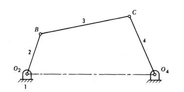
One of
the most useful and most common mechanisms is the four-bar linkage. In this
mechanism, the link which can make complete rotation is known as crank (link
2). The link which oscillates is known as rocker or lever (link 4). And the link
connecting these two is known as coupler (link 3). Link 1 is the frame.
Inversions of class 1 four bar mechanism
1.
When link 'b' is fixed : Crank Rocker or Crank Lever
mechanism, in the shortest link rotates 360 degree whereas the other link
oscillates
2.
When link 'a' is fixed : Crank Rocker or Crank Lever
mechanism, in the shortest link rotates 360 degree whereas the other link
oscillates
3.
When link 'd' is fixed : Drag link or Double crank mechanism in
which the links 'a' and 'b' undergoes complete 360 deg motion
4.
When link 'c' is fixed: Double rocker or Double lever mechanism
in which no link makes a complete rotation about its joints. In such case it is
similar to class 2 four bar mechanisms
A mechanism has been defined
above as a kinematic chain in which one of the links is fixed. From the four
bar mechanism, different versions of each of them can be obtained by fixing any
one of the links p, q l or s. Such different versions, which can be obtained by
fixing any of the different links, are called its “Inversions”.
Many a time, a particular inversion of a mechanism
may give rise to different mechanisms of practical utility, when the
proportions of the link lengths are changed. By this principle of inversion of
a four bar chain, several useful mechanisms can be obtained.
There are
three inversions of four bar mechanisms, which are obtained by fixing different
links of the kinematic chain.
They are:
a) Double Crank Mechanism
b) Crank Rocker Mechanism
c) Double Rocker Mechanism
d)
Parallel Crank Mechanism
2.2.1 Double Crank Mechanism
A double crank converts rotary motion from a crank to a
second crank or link in a different plane or axis. It is also known as
crank-crank, drag-crank or rotary-rotary converter. The links p, q and l shown
above rotate through one complete revolution. This is one of the first
inversions of four-bar mechanisms. In this discussion, let’s call the link‘s’
the frame as the fixed link. We will call the link ‘q’ the crank, ‘p’ the
coupler and ‘l’ the lever for now. Crank is not defined as the link, which is
attached to the driver shaft; rather it’s the link, which does a complete
revolution. And in this configuration, as there are two links, both q and l,
which revolves completely about the hinged point on the frame, both of them, is
cranks. The term is commonly used in automotive technology for the link in a
four bar steering linkage that converts rotation of a steering arm to a centre
link and eventually to tie-rod links which pivot the wheels to be steered. A
double crank is used when the steering arm operates in a plane above the other
links. The double crank converts the sweeping arc of the steering arm to linear
motion in the plane of the other steering links.
2.2.2 Crank-Rocker Mechanism
In
a four bar linkage, if the shorter side link revolves and the other rocks
(i.e., oscillates), it is called a crank-rocker mechanism. In this case, there
is only a slight change, leave the smallest side and connect any of its
adjacent side as the frame. Then (in figure) the smallest side ‘s’ will have
full 360 degree revolution while the other link adjacent to the frame has only
oscillating motion (link p). This kind of mechanism is hence called a
crank-lever mechanism or a crank-rocker mechanism or a rotary-oscillating
converter.
2.2.3 Double-Rocker Mechanism
A
linkage in which no link undergoes entire 360-degree revolution but only
oscillations is known as a double-lever mechanism. This linkage results
when the shortest side in the mechanism is made the coupler. The other two
links only get to oscillate in their place. A linkage in which the sum of the
longest and shortest link is less than the sum of the other two sides, is known
as a Class I mechanism, otherwise it’s Class II. This mechanism is achieved
when it is Class II. It’s also called rocker-rocker mechanism, double-rocker
mechanism or oscillating oscillating-converter.
2.2.4 Parallel Crank Mechanism
If in a 4 bar linkage, two opposite
links are parallel and equal in length, then any of the links can be made
fixed, regardless, the two adjacent links will always act as a pair of cranks,
i.e. , both will have complete revolution about their joints on the frame. The
use of such mechanism is made in coupled wheels of locomotives in which the
rotary motion of one wheel is transmitted to the other wheel.
2.3 Position
analysis of Grashof four bar mechanism
For
a planar four bar linkage, the sum of the shortest and longest links cannot be
greater than the sum of the remaining links if there is to be continuous
relative rotation between two members.
The position of the points on the
links A (Ax, Ay) and B (Bx, By) The coordinates of the point A are found using
trigonometry as follows:
Where,
|
|
|
|
|
|
|
|
The
link angles are given by
2.4 Planar four-bar linkage
Planar
four-bar linkages are constructed from four links connected in a loop by four
one degree of freedom joints. A joint may be either a revolute, which is a
hinged joint, denoted by R, or a prismatic, as sliding joint, denoted by P.
A link
connected to ground by a hinged joint is usually called a crank. A link
connected to ground by a prismatic joint is called a slider. Sliders are
sometimes considered to be cranks that have a hinged pivot at an extremely long
distance away perpendicular to the travel of the slider.
The link
that connects two cranks is called a floating link or coupler. A coupler that
connects a crank and a slider, it is often called a connecting rod.
There are
three basic types of planar four-bar linkage depending on the use of revolute
or prismatic joints:
1. Four
revolute joints: The planar quadrilateral linkage is formed by four links and
four revolute joints, denoted RRRR. It consists of two cranks connected by a
coupler.
2. Three
revolute joints and a prismatic joint: The slider-crank linkage is constructed
from four links connected by three revolute and one prismatic joint, or RRRP.
It can be constructed with crank and a slider connected by the connecting rod.
Or it can be constructed as a two cranks with the slider acting as the coupler,
known as an inverted slider-crank.
3. Two
revolute joints and two prismatic joints: The double slider is a PRRP linkage.
This linkage is constructed by connecting two sliders with a coupler link. If
the directions of movement of the two sliders are perpendicular then the
trajectories of the points in the coupler are ellipses and the linkage is known
as an elliptical trammel, or the Trammel of Archimedes.
Planar
four-bar linkages are important mechanisms found in machines. The kinematics
and dynamics of planar four-bar linkages are important topics in mechanical
engineering. Planar four-bar linkages can be designed to guide a wide variety
of movements.
2.5 Planar quadrilateral linkage
Planar
quadrilateral linkage, RRRR or 4R linkages have four rotating joints. One link
of the chain is usually fixed, and is called the ground link, fixed link, or
the frame. The two links connected to the frame are called the grounded links
and are generally the input and output links of the system, sometimes called
the input link and output link. The last link is the floating link, which is
also called a coupler or connecting rod because it connects an input to the
output. Assuming the frame is horizontal there are four possibilities for the
input and output links
A crank: can rotate a full 360 degrees
A rocker: can rotate through a limited range
of angles which does not include 0° or 180°
A 0-rocker: can rotate through a limited range
of angles which includes 0° but not 180°
A π-rocker: can rotate through a limited range
of angles which includes 180° but not 0°. Some authors do not distinguish
between the types of rocker
2.6 Design of four bar mechanisms
The
synthesis, or design, of four bar mechanisms is important when aiming to
produce a desired output motion for a specific input motion. In order to
minimize cost and maximize efficiency, a designer will choose the simplest
mechanism possible to accomplish the desired motion. When selecting a mechanism
type to be designed, link lengths must be determined by a process called
dimensional synthesis. Dimensional synthesis involves an iterate- and-analyze
methodology which in certain circumstances can be an inefficient process;
however, in unique scenarios, exact and detailed procedures to design an accurate
mechanism may not exist.
2.7 Systematic Diagram
2.8 Design and Fabrication Methodology:
Methodology to Design and Fabrication
the Box Sifting Mechanism
|
1.Analyse the problems in
Box Sifting Mechanism
|
|
2. Designing the required components.
|
|
3. Selection of required materials.
|
|
4. Purchasing the materials.
|
|
5. Fabrication of the Box Sifting
Mechanism
|
|
6. Preparation of report and
submit.
|
2.9 Selection of Materials
Linkages
Dc motor
Dc battery
Steel Frame
The design
and fabrication of box shifting mechanism constructed by various components
such as hylem board, dc wiper motor, dc battery, steel stand and wooden pieces.
In this steel frame build by using rectangular hollow pipes and steel rods
these are connected by welding operation. The hylem boards are cut by using
cutting operation. The dc wiper motor fitted on the frame by using bolt and nut
joint. Power supply given from the dc battery (12volts and 7amps) through
copper wires.
2.9.1 Linkages
A mechanical linkage is
an assembly of bodies connected to manage forces and movement. The movement of
a body, or link, is studied using geometry so the link is considered to be
rigid. The
connections between links are modeled as providing ideal movement, pure
rotation or sliding for example, and are called joints.
A linkage modeled as a network of rigid links and ideal joints is called
a kinematic chain. Linkages
may be constructed from open chains, closed chains, or a combination of open
and closed chains. Each link in a chain is connected by a joint to one or more
other links. Thus, a kinematic chain can be modeled as a graph in which the
links are paths and the joints are vertices, which is called a linkage graph.
The movement of an ideal joint is generally associated with a subgroup
of the group of Euclidean displacements. The number of parameters in the
subgroup is called the degrees of freedom (DOF)
of the joint. Mechanical linkages are usually designed to transform a given
input force and movement into a desired output force and movement.
The ratio of the output force to the input force is known as the
mechanical of the linkage, while the ratio of the input speed to the
output speed is known as the speed ratio. The speed
ratio and mechanical advantage are defined so they yield the same number in an
ideal linkage.
2.9.2 Dc motor
A windscreen wiper or windshield wiper is a device used
to remove rain and debris from a windscreen or windshield. Almost
all motor vehicles,
including trains, watercraft and
some aircraft, are
equipped with such wipers, which are usually a legal requirement. A wiper
generally consists of an arm, pivoting at one end and with a long rubber blade
attached to the other.
The blade is swung back and forth over the glass, pushing water from its
surface. The speed is normally adjustable, with several continuous speeds and
often one or more "intermittent" settings. Most automobiles use two
synchronized radial type arms, while many commercial vehicles use one or more pantograph arms.
2.9.3 Dc battery
A battery is a
device that can create electricity using
a chemical reaction. It converts energy stored in molecules inside the
battery into electricity. They produce direct current (DC)
electricity (electricity that flows in one direction, and does not switch back
and forth). Using the electricity from an outlet in a house or building is
cheaper and uses less energy, but a battery can provide electricity in areas
that do not have electric power distribution. It is also
useful for things that moved around and cords would get in the way.
2.9.4 Steel Frame
Steel frame is a building
technique with a "skeleton frame" of vertical steel columns and horizontal I-beams, constructed in a rectangular grid to support the floors, roof and
walls of a building which are all attached to the frame. The development of
this technique made the construction of the skyscraper possible.
2.10 WORK PLAN
STAGE1: Collecting the Materials
The links
are drawn by using the auto cad 2010 software then this diagram printed in a A2
sheet. Then hylem sheet brought from a hylem shop dimension 610*420. Then paste
the A2 sheet on the hylem then it will be cutted by using cutting machine and
it drilled by the drilling machine
Dc wiper motor and dc battery brought
from an automobile spare shop. After completing these works the frame would be
designed in welding work shop
STAGE 2: Fabrication of Components
The following components are
fabricated for the box shifting machine
Dc battery
It is used to run the wiper motor.
When power required then that time it give the power to the wiper motor.
Dc motor
It is used run the whole linkages.
Bolt and Nut
It is used to connect the linkages and
used to fix linkages on the frame.
Steel Frame
It is used hold whole parts of this
machine. It is made by using G.I rectangular pipes and sheets.
Linkages
These linkages are made by using hylem
boards done by cutting operation
STAGE 3:
Process for Fabrication
Welding
In welding process, the electric arc is used to melt the two metals and
joint them permanently. Electrode is used to produce electric arc .The gap
between electrode and metal is 3mm. If welding is overlapped, it affects the
quality of metal joint. It is used to inter connect the columns.
Metal Cutting
The square circular shaft and hylem board cut for our required dimension
by using metal cutter. The circular shaft acts a column of box shifting
machine. The hylem pieces are act as linkages. Metal cutter cuts all material
to required dimension.
Drilling
Drilling is used to screwing the screw through the
drilling. To tight the linkages, the screw is screwing through the drilling and
helps to fix the linkages.
STAGE 4: Assembling the Components
All the
components are assembled in a correct manner. Then is will be re checked again
and undergoes to the painting process
CHAPTER 3
APPLICATION
·
We can usedthis mechanism in medical production fields.
·
We can used this mechanism in bottle filling process
·
We can used this mechanism in cool drinks production
companies.
ADVANTAGES
·
Lubricants not required.
·
Simple to construct.
·
Low speed motor is sufficient
·
Easy maintenance.
·
Less skilled operator is sufficient.
·
Noise of operation is reduced.
MODIFICATIONS
1. Using
solar panel we able to run this motor we get more efficiency
2. We are
modify it to remove hylem board and use aluminum plate
CHAPTER 4
CONCLUSION
The box shifting mechanism plays a major role in industries, the process
of transporting or shifting products from one place to another was to be
maintained by conveyors only. So we just successfully altered this with a box
shifting mechanism using the kinematics links and a motor. We had just
implemented our basic mechanical knowledge and designing skills for designing
and fabricating this project successfully.
REFERENCES
· “A Review on Kinematic and Dynamic Analysis of Mechanism” by Shrikant R.
Patel, D. S. Patel, B. D. Patel Research Scholar, Associate Professor,
Assistant Professor
· “Dynamic modeling and
identification of a slider-crank mechanism” by
Jih-Lian Haa , Rong-Fong Fungb, Kun-Yung Chenb , Shao-Chien Hsienb
·
“Kinematics and kinetic analysis of the slider-crank
mechanism in otto linear four cylinder Z24 engine” Mohammad Ranjbarkohan,
Mansour Rasekh , Abdol Hamid Hoseini , Kamran Kheiralipour and Mohammad Reza
Asadi
· http://en.wikipedia.org/wiki/Crank_(mechanism)
·
A Text Book of Automobile Engineering by R. K.
Rajput
No comments:
Post a Comment
Thank You